Composite hoses are primarily used for the transfer of aromatic chemicals and liquefied gases with cryogenic properties. They are more flexible and lighter weight than conventional rubber hoses – but if not used correctly, they may be prone to failure, leading to both environmental pollution and financial loss.
Know Your Hoses
Composite hoses and hose assemblies for the transfer of hydrocarbons, solvents, and chemicals are manufactured to the international European standard EN 13765:2018, which specifies:
- Bore sizes from 25 mm to 300 mm
- Working pressures from + bar to 14 bar
- Working temperatures from 30° C to 150° C
These hoses may be one of four types. Type 1 is suitable for vapor applications. Type 2, Type 3, and Type 4 are suitable for liquid applications. Types 3 and Type 4 are used for STS (Ship-to-Ship Transfers).
Composite hoses and hose assemblies for the transfer of liquid petroleum gas and liquefied natural gas are manufactured to the standard EN 13766:
- Bore sizes from 25 mm to 250 mm
- Working pressures from 10.5 bar to 25 bar
- Working temperatures from -196° C to +45° C
These hoses are divided into Type 1 and Type 2, depending on pressure and temperature ratings.
They are subdivided into two classes: Class A for onshore duties and Class B for offshore duties (STS).
Construction
A composite hose is manufactured in three sections:
- Inner high-tensile wire helix
- Reinforcement and protective liquid-tight layers
- Outer high-tensile wire helix
The inner helix wire is made of cargo-compatible metal, with the pitch (distance between each wire) corresponding to that of the outer wire. It acts as inner support to prevent the hose from collapsing under vacuum. It supports the inner liver and reinforcement fabric layers.
The outer helix wire forms an interlocking pattern with the inner helix wire, providing external strength to the hose and enabling it to achieve the desired working pressure and structural integrity. It binds the various reinforcement layers within the outer and inner helix wires and acts as a protective external barrier to prevent the hose from mechanical abrasions during operation.
Components of Hose
Liner: The innermost protective layer in a composite hose is in direct contact with the product.
When selecting a composite hose, always check that the liner material is compatible with the product being transferred.
Reinforcement/Sealing layer: Various thermoplastics and reinforcement materials may be used, depending on the product for which the hose is intended. These may include polyvinyl chloride (PVC), polytetrafluoroethylene (PTFE), polypropylene, polyamide, and acrylic.
End fittings: Every composite hose is provided with end fittings, either epoxy wet-sealed or crimped dry-sealed. A typical composite hose used in maritime applications is equipped with either a fixed flange or a floating flange.
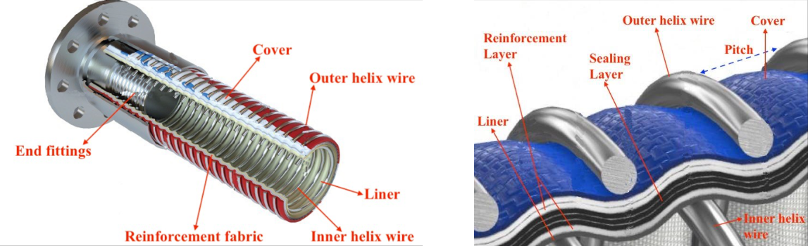
A typical cross-sectional design and section of a composite hose
Flange Standards and Design
Composite hose flange(s) may be fabricated using either stainless steel (like SUS 316L) or mild carbon steel, depending on their use. Selection criteria are dependent on:
- Diameter of the composite hose
- Designed pressure
- Temperature of operation
Typically, an ANSI Class 150 composite hose is used for the transfer of hydrocarbons, solvents, and chemicals, whereas an ANSI Class 300 composite hose is used for the transfer of liquid petroleum gas.
A composite hose flange typically has a raised face floating flange, as opposed to a flat face fixed flange, which is commonly found on rubber hoses.
A typical raised face flange has a raised surface above the bolting circle where the gasket is placed. Effective sealing on this type of flange face is accomplished by compressing a soft, flat, or semi-metallic gasket between mating flanges in the raised area of the flanges.
Both raised and flat face flanges may he either floating or fixed. A floating flange allows for faster and easier connection to the manifold without the need to turn the hose to align the bolt holes.
Identification Markings
The operational specification of the hose must be permanently marked on the outer cover by the manufacturer, usually with a tape or band. For hoses exposed to very low temperatures, for example, during the transfer of LPG or LNG, the specification may be permanently stamped/etched on the flange body.
Typical hose markings include:
- Maker’s details
- Hose material and diameter of hose
- Construction standard CEN 13765PEN 137664
- Type number
- Maximum working pressure (MWP)
- Permissible working temperature
- Year and quarter manufacturing
The operator must ensure that every composite hose in operation complies with the applicable design standards for the cargo grade. In addition to the maker’s test certificate accompanying each composite hose, a hose shall be type approved by the vessel’s classification society and shall also comply with the local regulations, if applicable.
The manufacturer of a composite hose must provide a cargo grade compatibility chart for the hose. The user must verify the chemical properties of the product and the suitability of the composite hose before use.
Factors Affecting Integrity of Composite Hose
The structural integrity of a composite hose is affected by the following factors:
Operating temperature range: The manufacturer provides the minimum and maximum permissible temperature ranges for a composite hose. Using a composite hose outside the recommended temperature range can severely affect the structural integrity of the liner. The properties of the thermoplastics used in composite hoses mean that elevated temperatures are always a disadvantage.
Operations at temperatures typically above 60° C can cause elongation of the hose, which will then require suitable support. At elevated temperatures, a composite hose that is not properly supported may undergo plastic deformation, resulting in possible displacement of the helical wire support and catastrophic failure.
Operating pressure range: The Maximum Working Pressure (MWP) is set by the manufacturer. Operation under both elevated pressure and elevated temperature is not recommended. A sudden pressure surge can lead to elongation of the hose, which risks displacing the internal helical wire support.
Minimum Bend Radius (MBR): The MBR is provided by the manufacturer. Bending a composite hose beyond the recommended MBR can permanently displace the helical wire, leading to rupture. Again, the hose should be adequately supported throughout its entire length, especially near the end fittings. The composite hose should never be stowed, coiled, or secured by kinking/bending/coiling beyond the recommended MBR.
Flow rate: The manufacturer provides the permissible flow rate, which is dependent on:
- Length of hose
- Diameter of hose
- Viscosity of cargo
Due to the internal helical wire design, a composite hose is subjected to higher frictional and pressure losses than a comparable smooth-bore rubber hose.
Products with higher viscosity and/or higher flow rates will cause a notable drop in pressure across the composite hose, which could eventually displace the inner helical wire support and collapse the hose.
Any abnormal and/or unexplained increase in pressure or reduction of flow rate across the composite hose shall he treated with concern. Immediately stop cargo operations and conduct a thorough internal inspection of the hose.
ISGOTT 18.2.5 defines the maximum flow rates (m3/hour) for a bore size of a composite hose. Typical recommended velocities for a composite hose are 7 to 9 m/s.
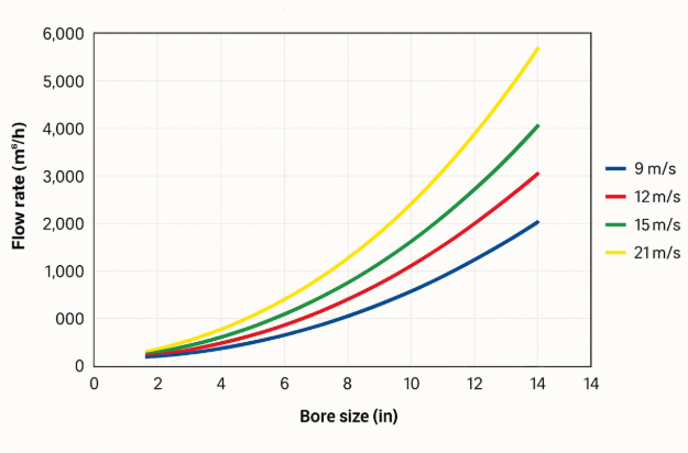
Graph courtesy: ISGOTT Section 18.2.5
Pressure Testing
Composite hoses should he tested according to the procedures set out in ISGOTT 18.2.6.3. The besting interval shall never exceed 12 months. If temporary elongation is in excess of 10% during pressure testing, then the composite hose shall be withdrawn from service.
Electrical continuity shall always be ensured before and after the pressure testing of the composite hose.
Terms commonly used in pressure testing include:
Maximum Working Pressure (MWP): Maximum hose pressure capability. This pressure testing is expected to account for dynamic surge pressures and is used by BS and EN Standards for designing hoses.
Rated Working Pressure (RWP): The working pressure expected during normal working conditions. Does not take into account dynamic surge pressures and is not to be confused with MWP.
Factory Test Pressure: This is referenced in BS EN 1765 and is defined as equal to the MWP.
Maximum Allowable Working Pressure (MAWP): Used as a reference by the United States Coast Guard (USCG) and commonly used by terminals to define their safety equipment limitations.
Hydrostatic Test Pressure: The pressure at which the hose is tested at least annually.
Proof Pressure: A one-time pressure applied to production hoses to ensure integrity following manufacture. Equal to 1.5 times the MWP.
Burst Test Pressure: A test requirement for a single prototype hose to confirm the hose design by the manufacturer. The pressure is equal to a minimum of four (4) times the factory test pressure. It must be applied in a specific manner and held for 15 minutes without hose failure.
Burst Pressure: This is the actual pressure at which a prototype hose fails. For a successful prototype hose, the burst pressure would exceed the Burst Test Pressure.
Visual and Routine Inspections
The operator must routinely carry out a thorough visual inspection of the composite hose as per the manufacturer’s directives. Records of operations (product/grade), handling, and routines shall be maintained onboard throughout the handling and service life of the hose.
This article, authored by Sanjeev Kumar Gupta, was also published in August 2022 by the Nautical Institute (Seaways).